Line to ground fault occurs most-> 70 to 80% Line to Line fault -> 15-20% Double Line fault-> less than 10%
Line to ground fault occurs most-> 70 to 80%
Line to Line fault -> 15-20%
Double Line fault-> less than 10%
See lessLost your password? Please enter your email address. You will receive a link and will create a new password via email.
Please briefly explain why you feel this question should be reported.
Please briefly explain why you feel this answer should be reported.
Please briefly explain why you feel this user should be reported.
The figure shows the single line diagram of a sample power system, a double line to ground fault occurs on phase of b and c at the point F in the system. Find the fault current at the fault point. ...Read more
The figure shows the single line diagram of a sample power system, a double line to ground fault occurs on phase of b and c at the point F in the system. Find the fault current at the fault point. The machines are rated 1.2 MVA, 0.6 kV with X1=X2=0.10 PU and X0=0.05 PU. Transformers are 1.2 MVA each with leakage reactance of 0.05 PU. Transmission line reactances are XL1=XL2=0.20 PU and XL0=0.4 PU on the MVA base of machines. 
A dead earth fault occurs on one conductor of a 3-phase cable supplied by a 5000 kVA, 3-phase generator with earthed neutral. The sequence impedances of the alternator are given by Z1=(0.4+j4)ohm; Z2=(0.3+j0.6)ohm and Z0=(0+j0.45)ohm per phase. The sequence impedance ...Read more
A dead earth fault occurs on one conductor of a 3-phase cable supplied by a 5000 kVA, 3-phase generator with earthed neutral. The sequence impedances of the alternator are given by Z1=(0.4+j4)ohm; Z2=(0.3+j0.6)ohm and Z0=(0+j0.45)ohm per phase. The sequence impedance of the line up to the point of fault are (0.2+j0.3)ohm, (0.2+j0.3)ohm, (0.2+j0.3)ohm and (3+j1)ohm. Find the fault current and the sequence components of the fault current. Also find the line to earth voltages on the in faulted lines. The generator line voltage is 6.6kV.
Read lessThe system data for a load flow solution are given in tables. Using Newton-Raphson method, determine the voltage at bus-2 the end of the first iteration. Line from-To Admittance 1-2 10-j20 1-3 10-j30 2-3 16-j32 Bus no. P(pu) Q(pu) V(pu) Remarks 1 – – 1.05+j0 Slack 2 4 2.5 1+j0 PQ 3 2 15 1+j0 PQ
The system data for a load flow solution are given in tables. Using Newton-Raphson method, determine the voltage at bus-2 the end of the first iteration.
| Line from-To | Admittance |
| 1-2 | 10-j20 |
| 1-3 | 10-j30 |
| 2-3 | 16-j32 |
| Bus no. | P(pu) | Q(pu) | V(pu) | Remarks |
| 1 | – | – | 1.05+j0 | Slack |
| 2 | 4 | 2.5 | 1+j0 | PQ |
| 3 | 2 | 15 | 1+j0 | PQ |
Read less
Determine the fault current when a double line to ground fault occurs at the terminals of the alternator.
Determine the fault current when a double line to ground fault occurs at the terminals of the alternator.
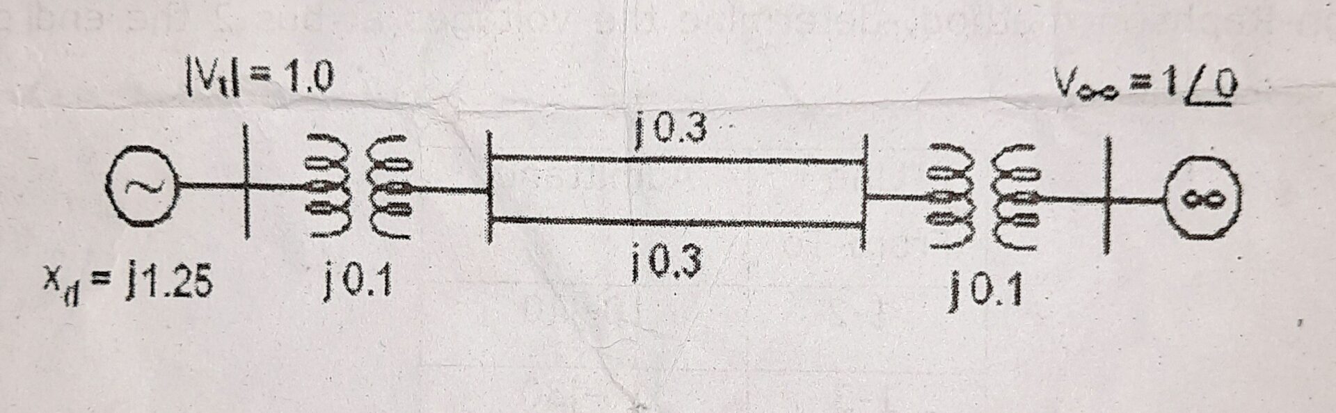
Read lessA generator supplies 1.0 p.u. power to an infinite bus as shown in the figure. The terminal voltage and infinite bus voltage are 1.0 p.u.All the reactances are on a common base. Determine steady state stability limit: When both lines are ...Read more
A generator supplies 1.0 p.u. power to an infinite bus as shown in the figure. The terminal voltage and infinite bus voltage are 1.0 p.u.All the reactances are on a common base. Determine steady state stability limit:
Read less
The methods often employed in practice to improve system stability are: Increasing System Voltage: ... Reduction in Transfer Reactance: ... Using High Speed Circuit Breaker: ... Automatic Reclosing: ... Transient Stability: ... Turbine Fast Valving: ... Application of Braking Resistors: ... Single PRead more
The methods often employed in practice to improve system stability are:
- Increasing System Voltage: …
- Reduction in Transfer Reactance: …
- Using High Speed Circuit Breaker: …
- Automatic Reclosing: …
- Transient Stability: …
- Turbine Fast Valving: …
- Application of Braking Resistors: …
- Single Pole Switching:
See less